3D is the source of truth for project management; 2D is the source of truth for fabrication.
The two halves are lopsided in opposite directions. 3D is almost all of the bytes and almost none of the files: ~22K files holding 5,621.0 GB. The drawings, cut outlines and machine programs on the 2D side run to 1,193.9 GB across vastly more files.
3D — 17,410 models (IFC + STEP)
~22K files, 5,621.0 GB. The coordination record.
The model is where the job gets put together and checked. Architects, structural engineers and site teams use it to confirm the pieces fit before anything is cut — one model covers what thousands of sheets detail one at a time.
What is in them is the steel itself: assemblies of members and plates with their bolts, welds, stairs and railings, each carrying its own mark. One 6.1 MB IFC holds 68 assemblies, 550 members, 125 plates and 4 stairs.
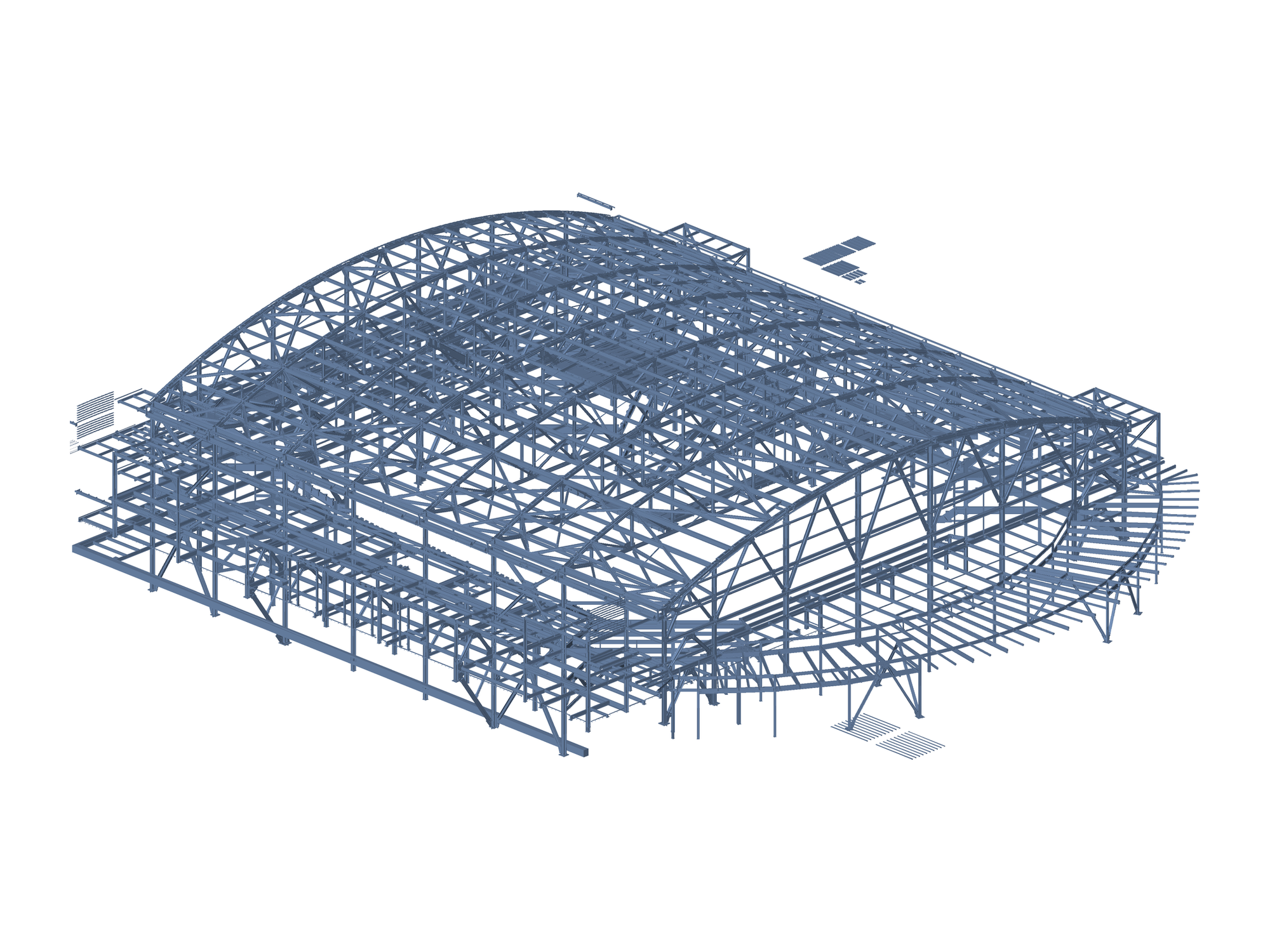
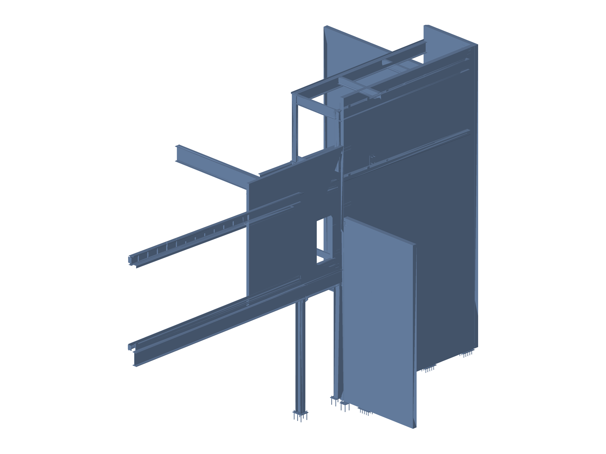
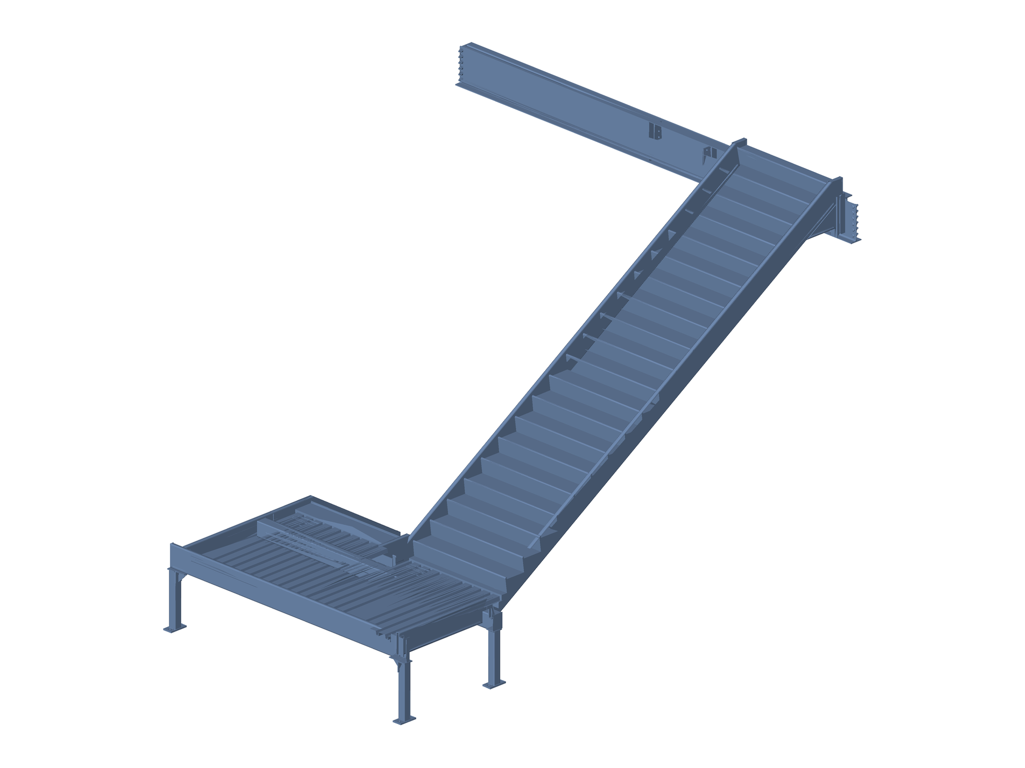
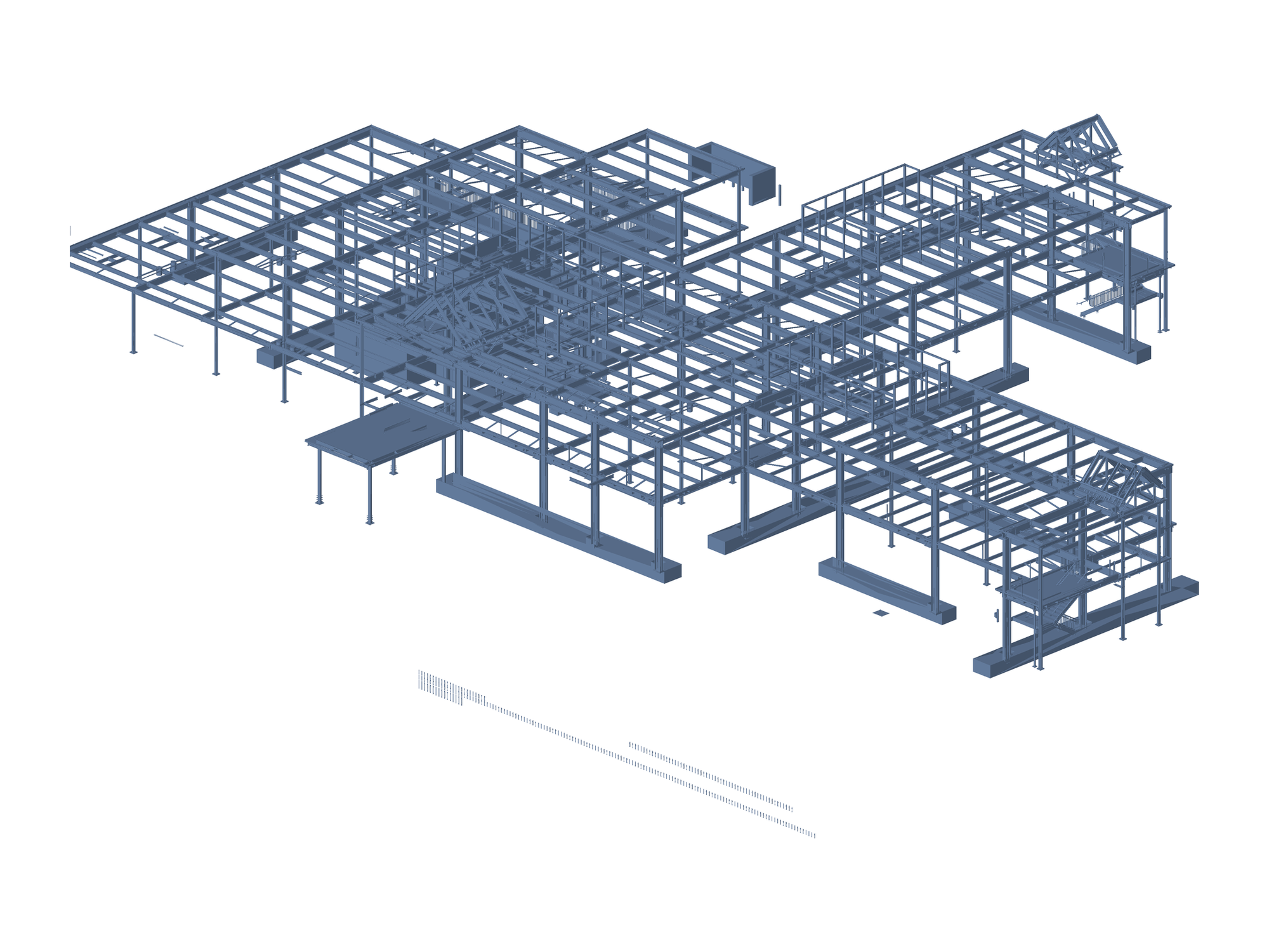
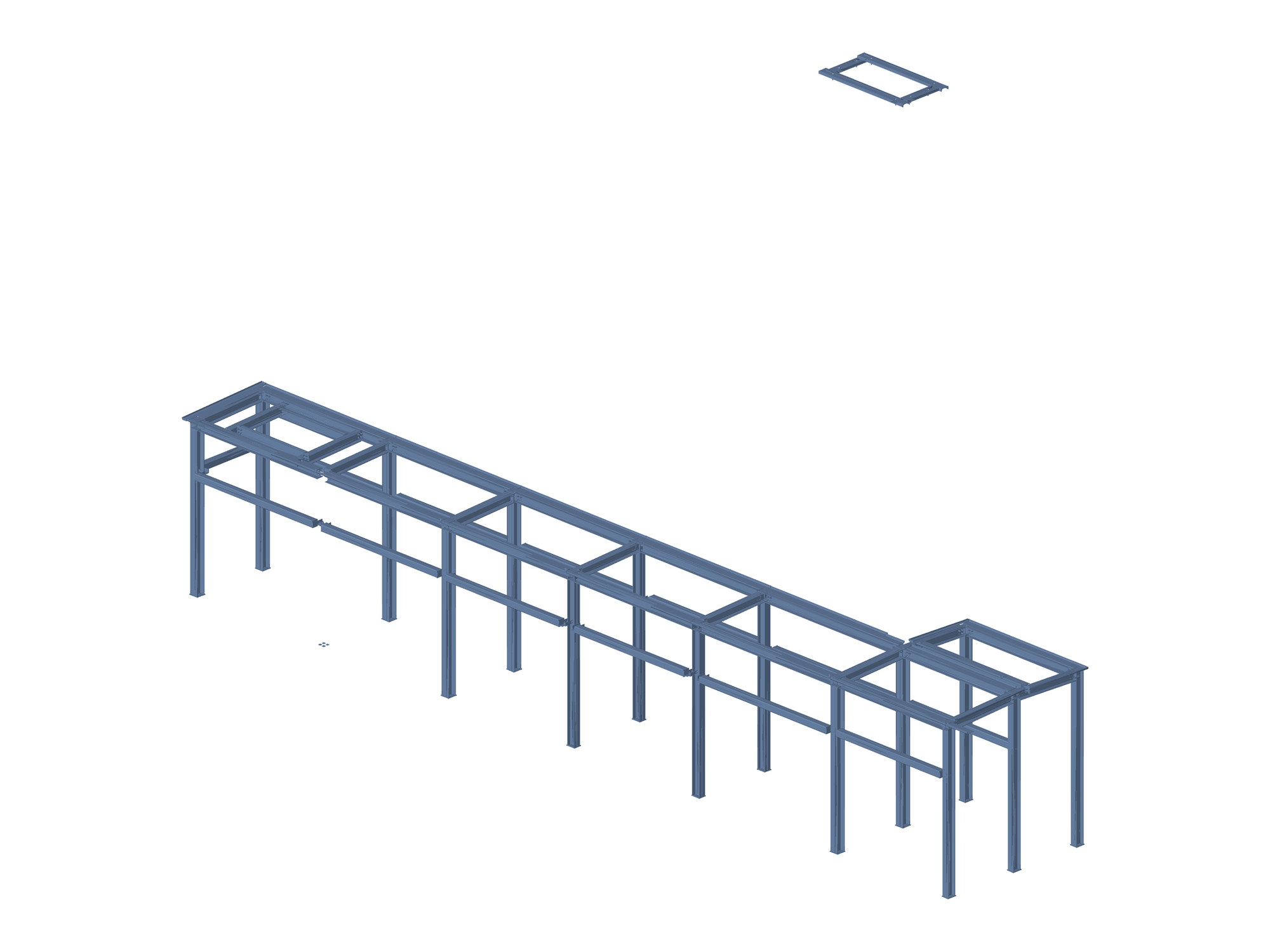
Five models at five scales. Press “interact” to load the geometry, then drag to rotate or scroll to zoom.
| File class | Distinct files | Volume (GB) |
|---|---|---|
| STEP models | 13,461 | 5,346.7 |
| IFC models | 8,211 | 268.2 |
| Tekla model databases | 1,130 | 6.1 |
The Tekla row is the authoring format — the model a detailing office works in, holding the parametric connections, the assembly structure and the fabrication attributes that an exchange format has nowhere to put.
A model is one named piece of geometry: 4,082 are carried as both STEP and IFC, 9,256 as STEP only and 4,072 as IFC only; a model held in both formats counts once. The 17,410 covers IFC and STEP; the file count above covers all three.
2D — the fabrication record
~2.9M drawings: vector CAD, DWG and DXF. The machine programs are a separate layer, counted below.
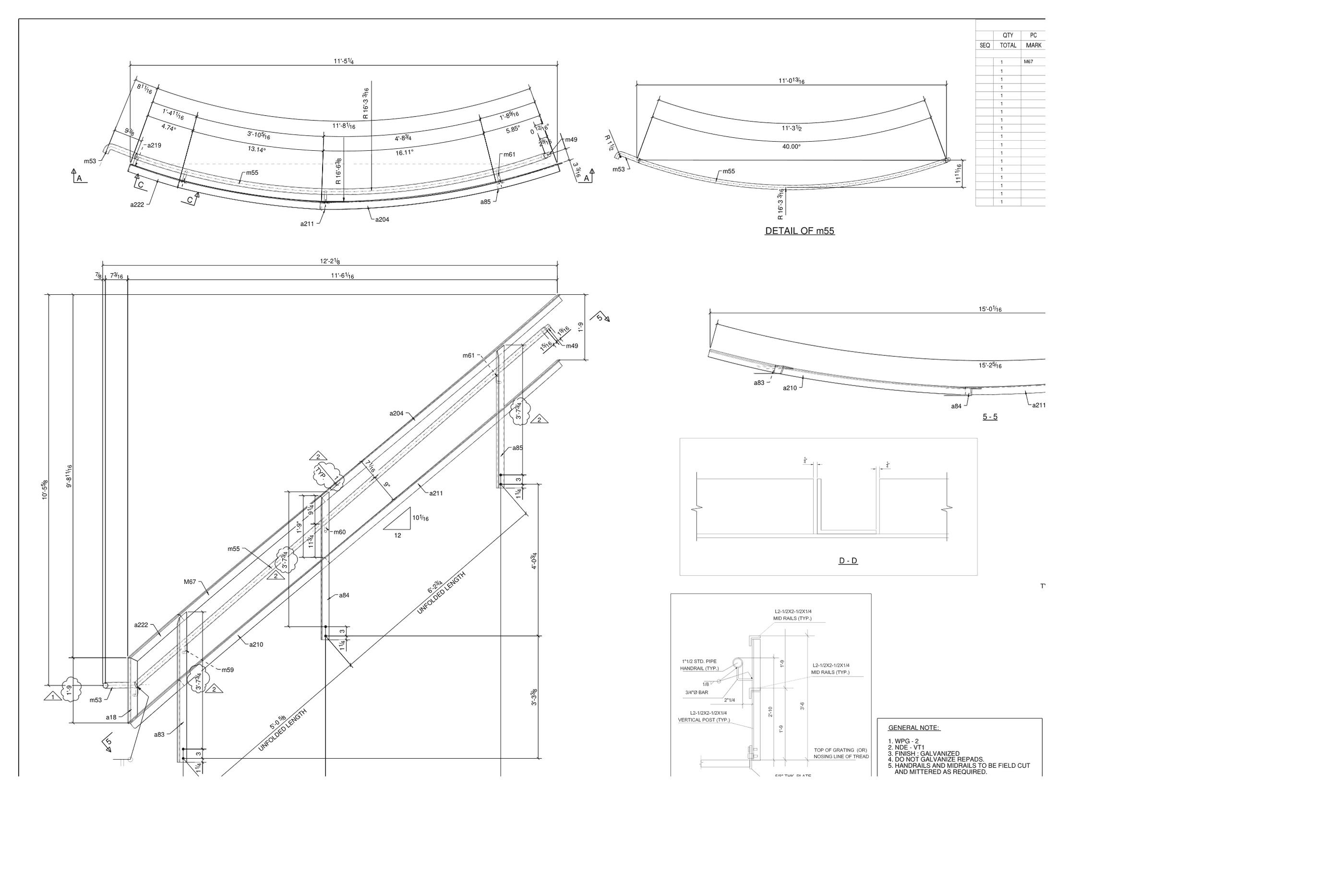
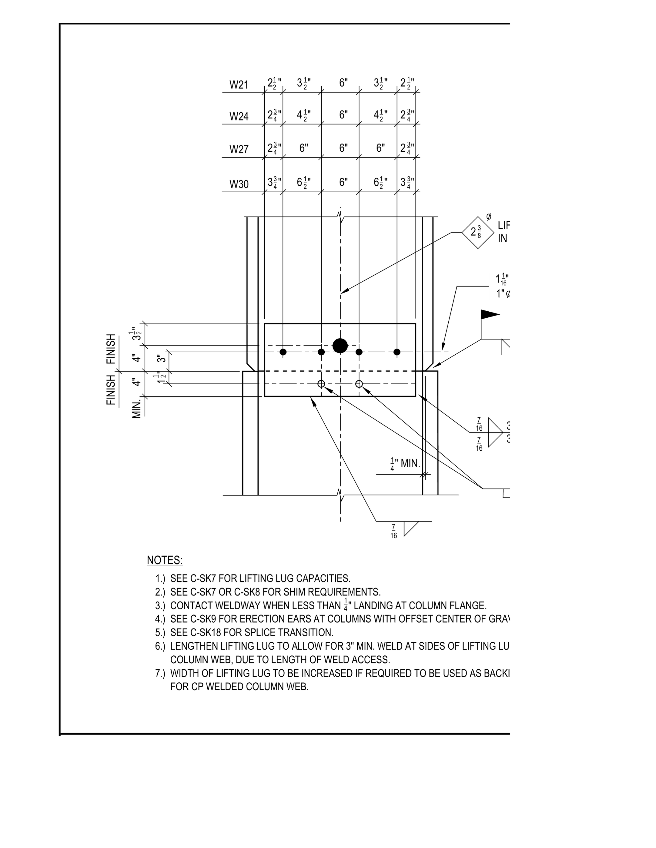
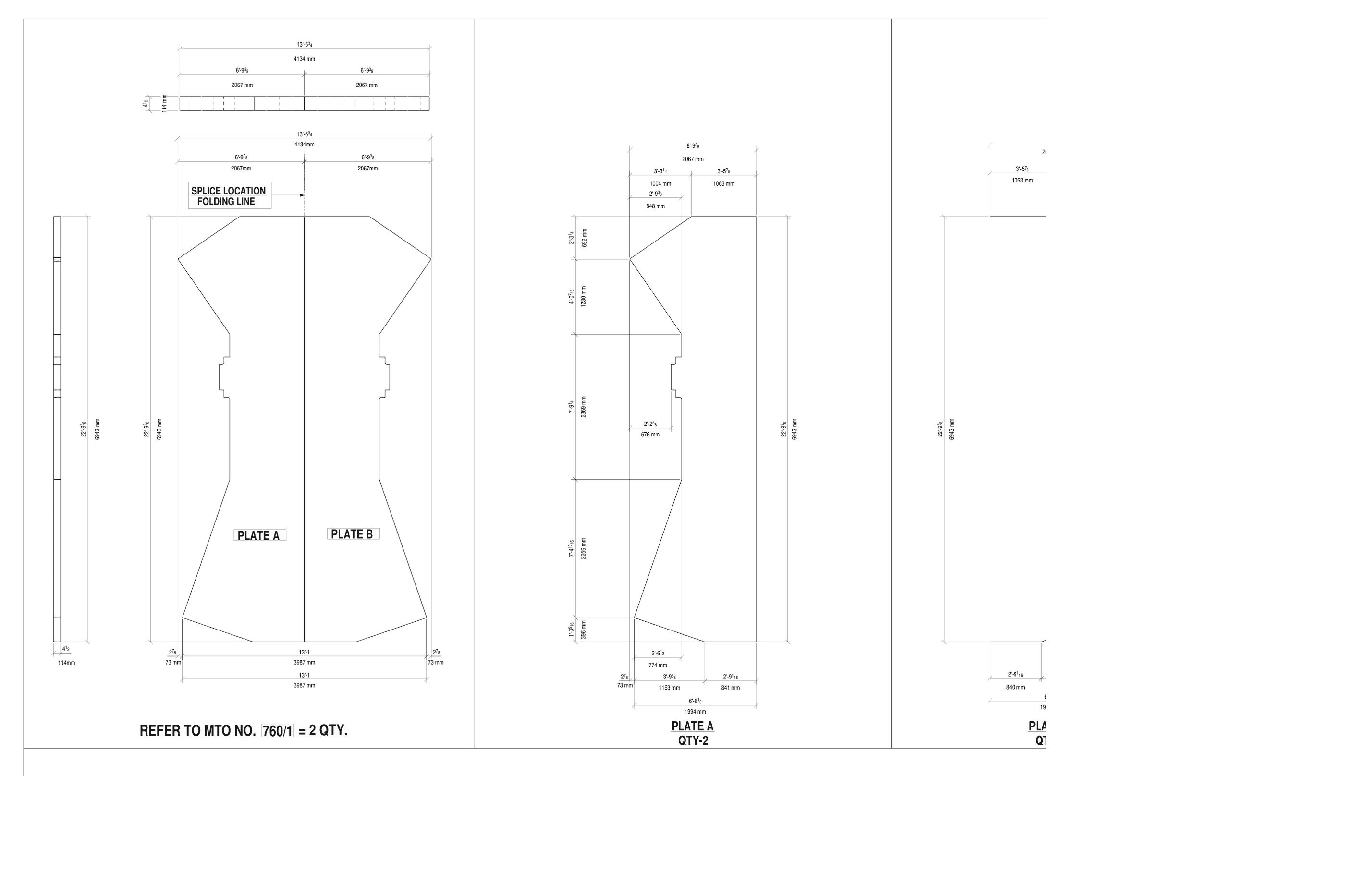
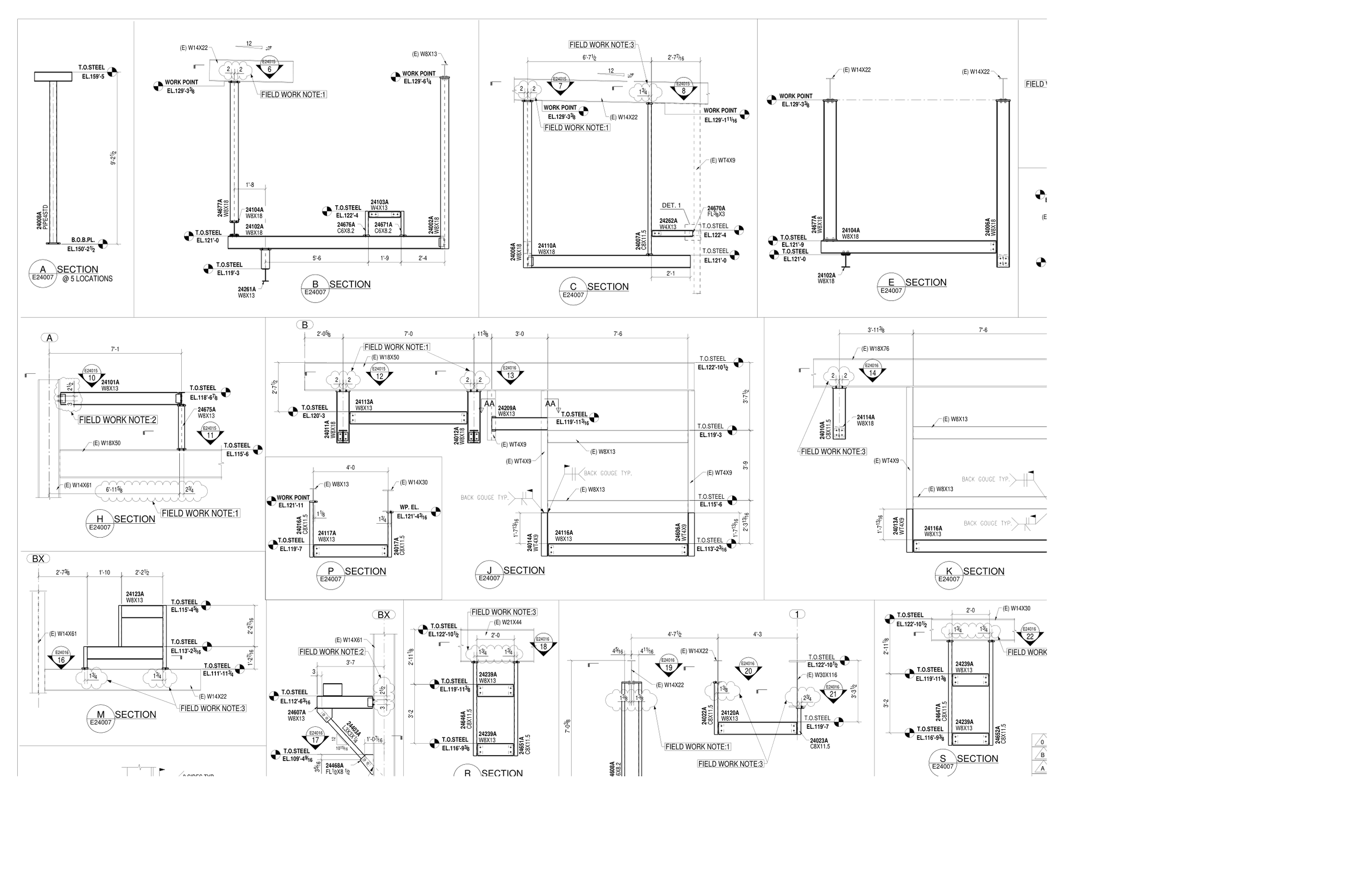
These are the drawings a fabricator builds from: the source of truth for making the metal that goes into a building, a plant or a pipeline. Each sheet details every bolt and joint — placement, angle, hole size, weld symbol, steel grade — and carries dimensions to the hundredth of a millimetre. Get one wrong and the structure does not hold.
And they really are drawings: ~2.2M are vector CAD, so the lines, the text and the dimension strings are geometry.
 Full size ↗
 Full size ↗
 Full size ↗
 Full size ↗
 Full size ↗
 Full size ↗
 Full size ↗
 Full size ↗
 Full size ↗
 Full size ↗
 Full size ↗
 Full size ↗
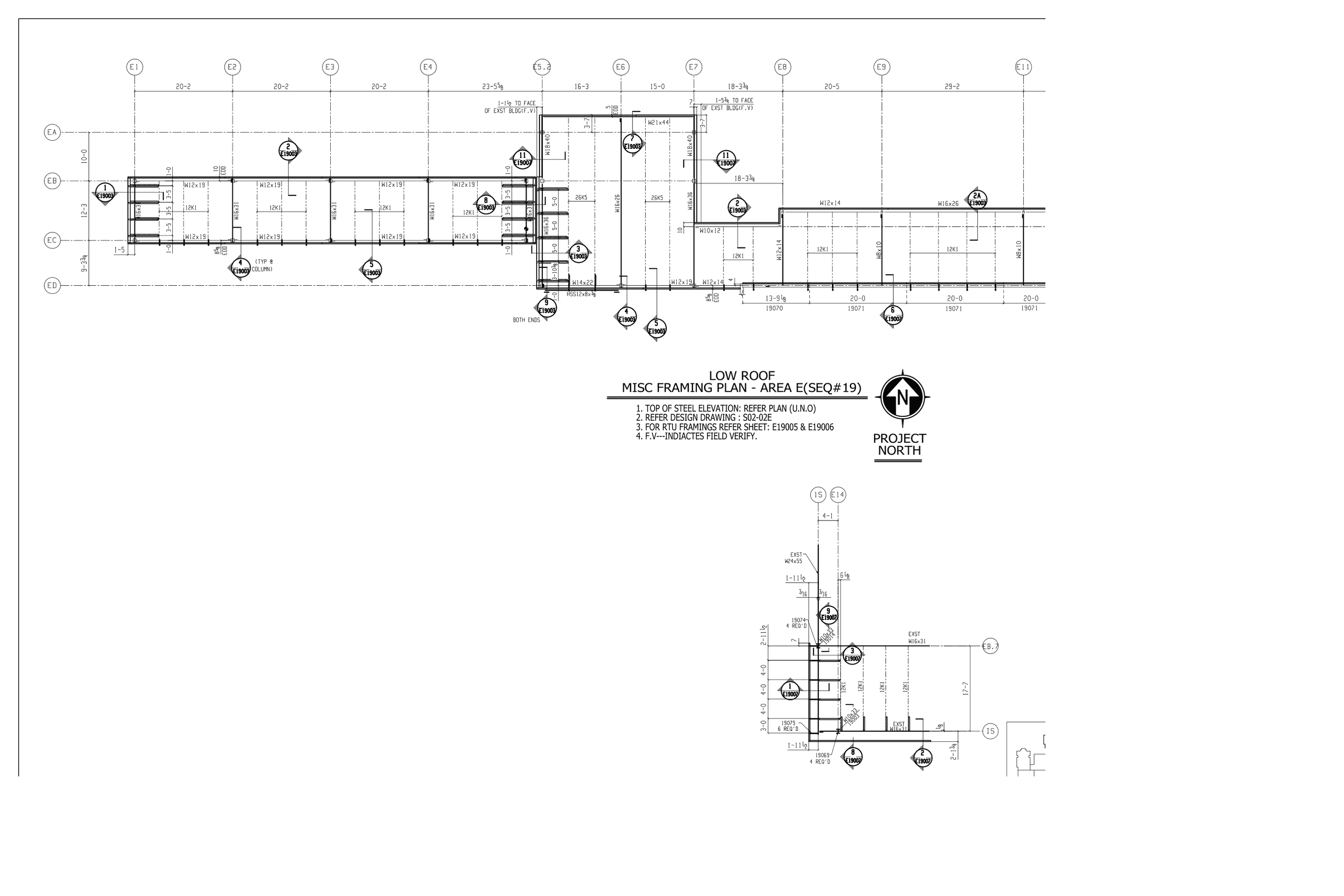
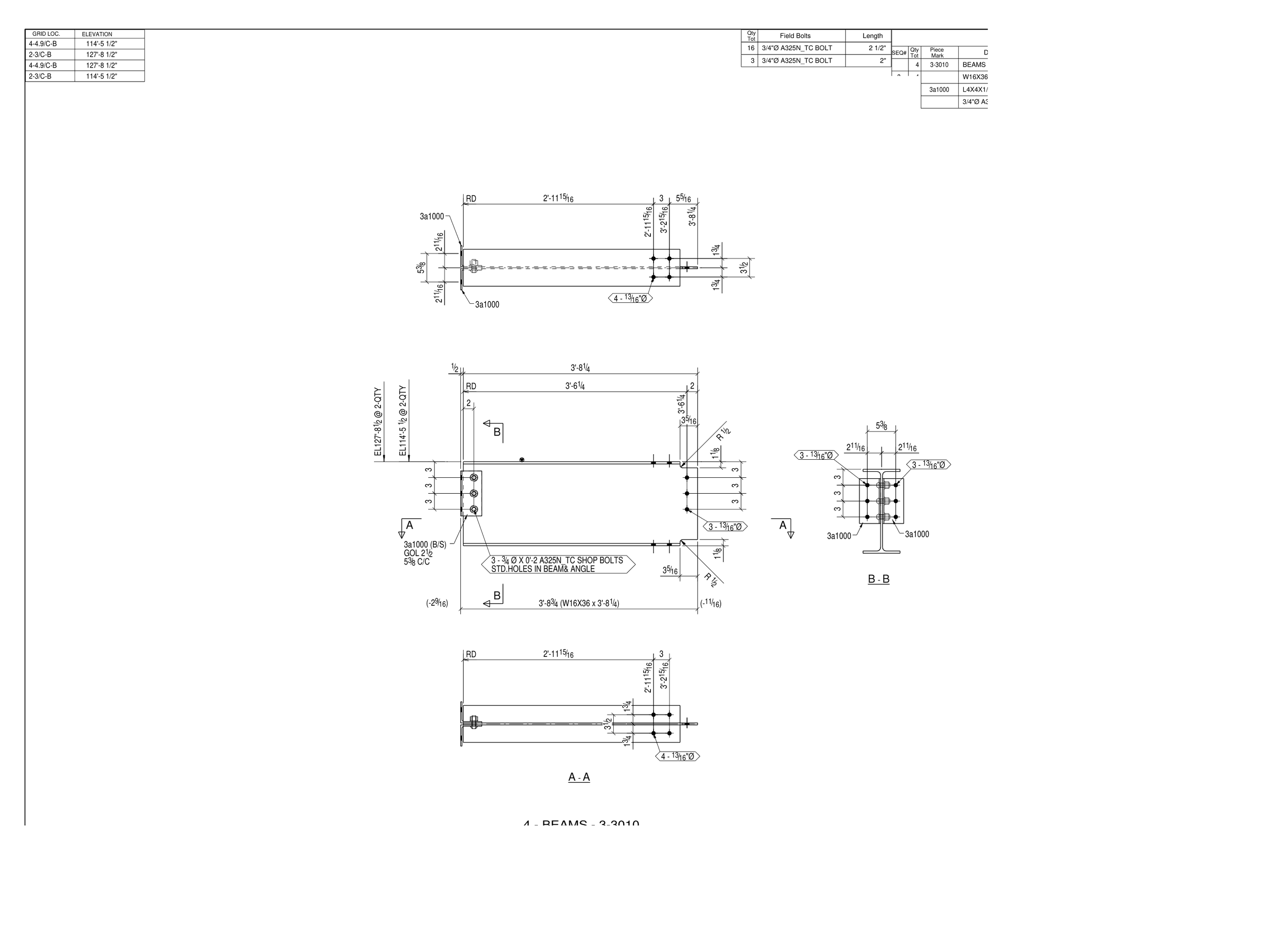
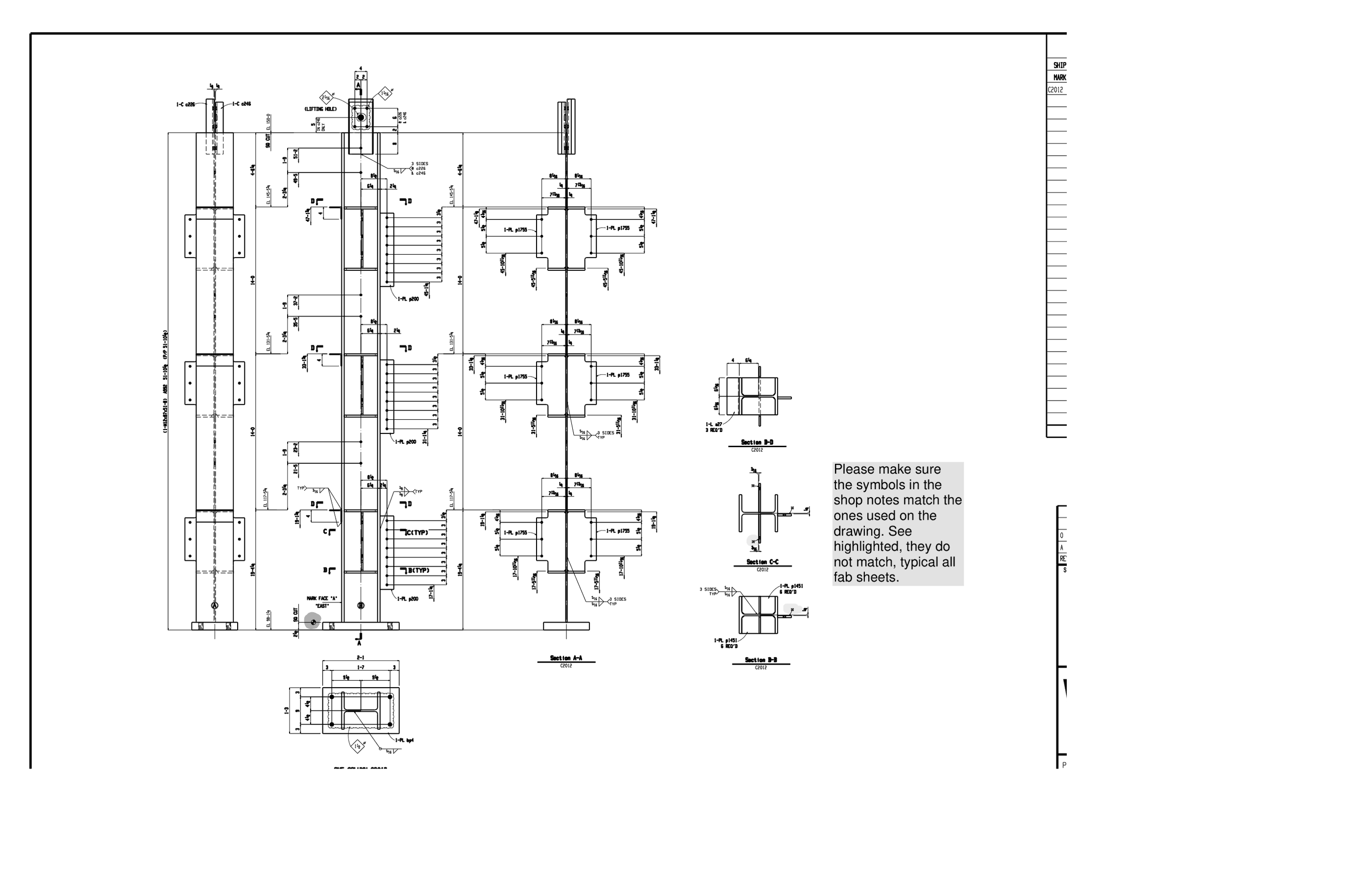
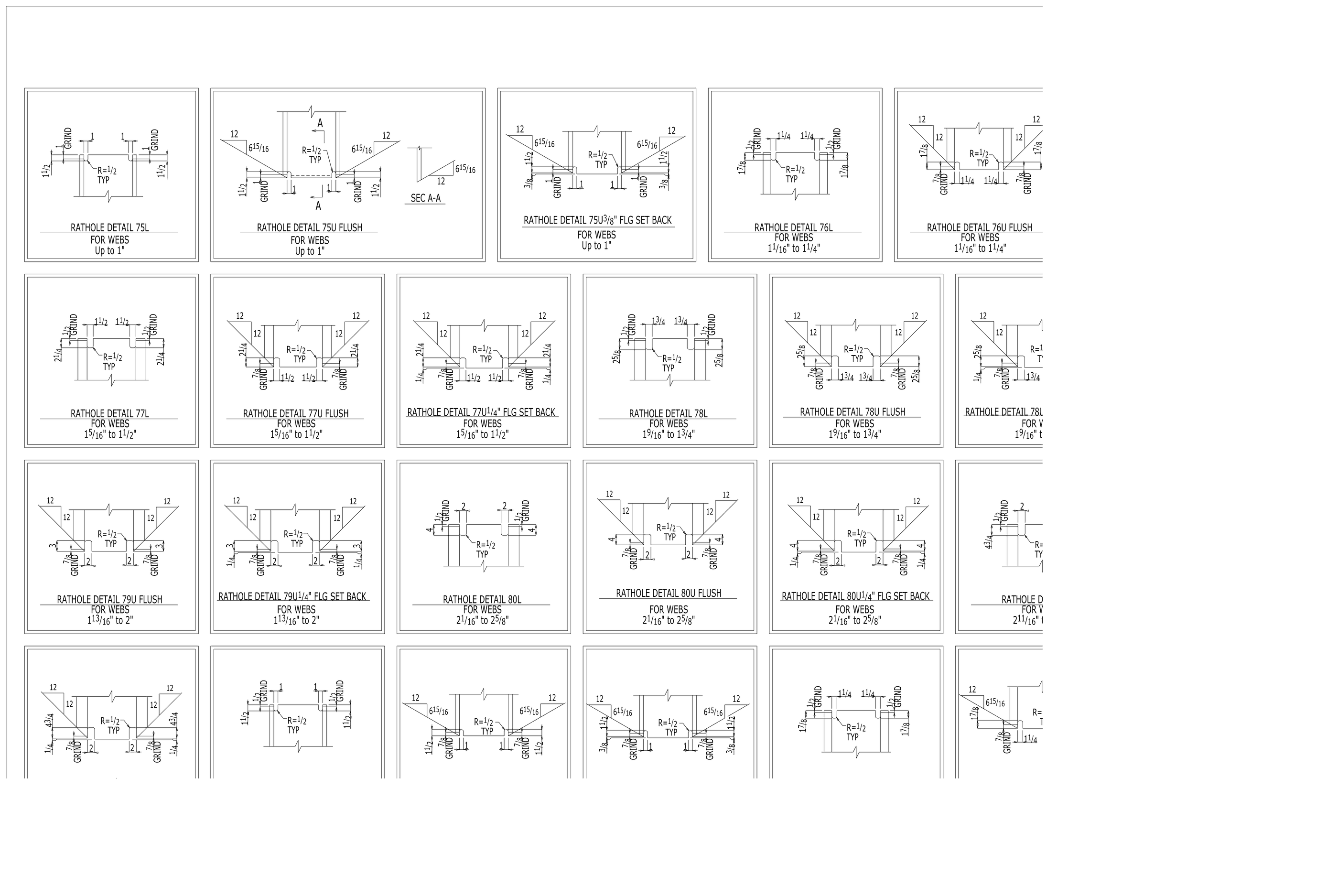
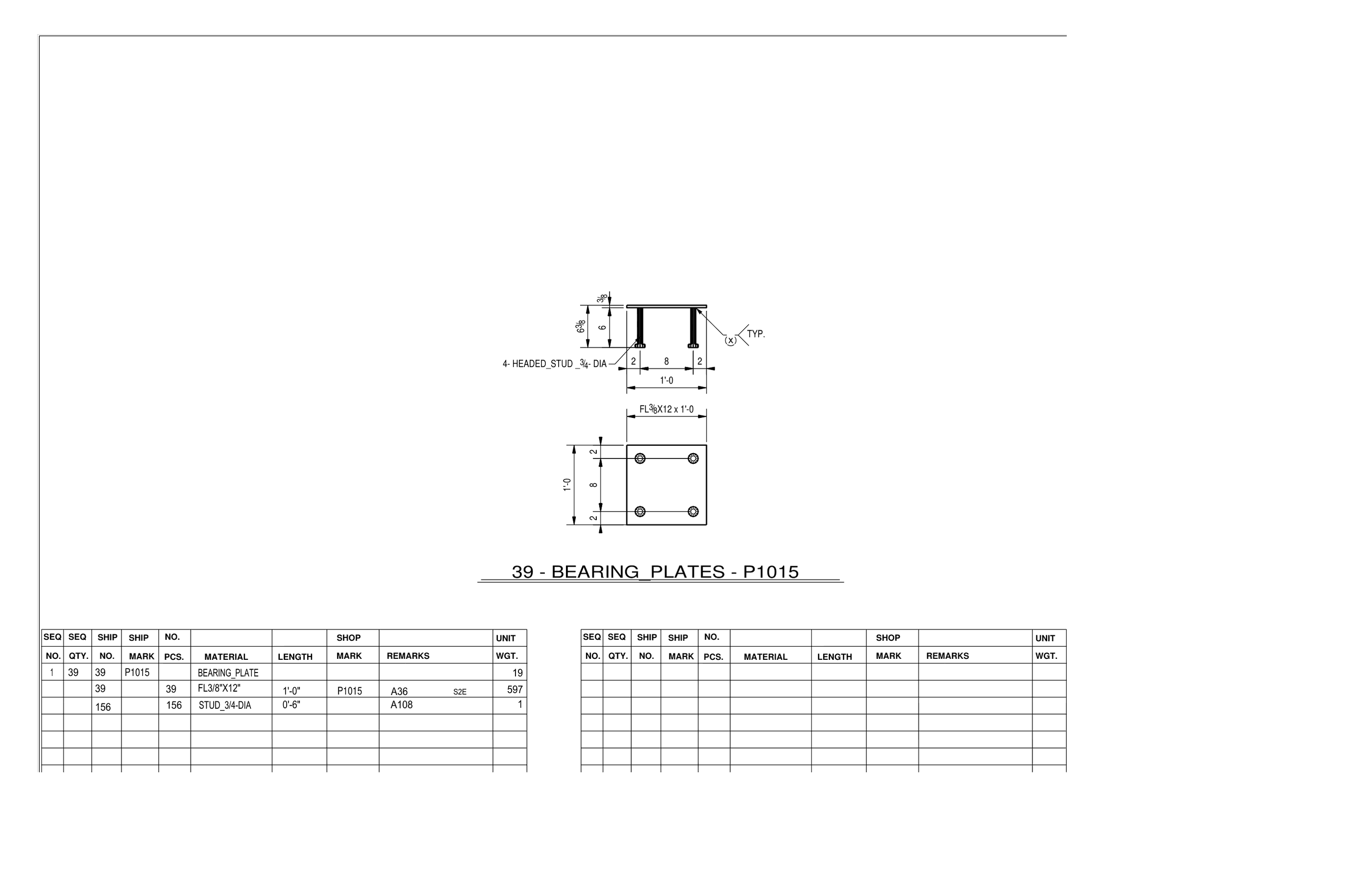
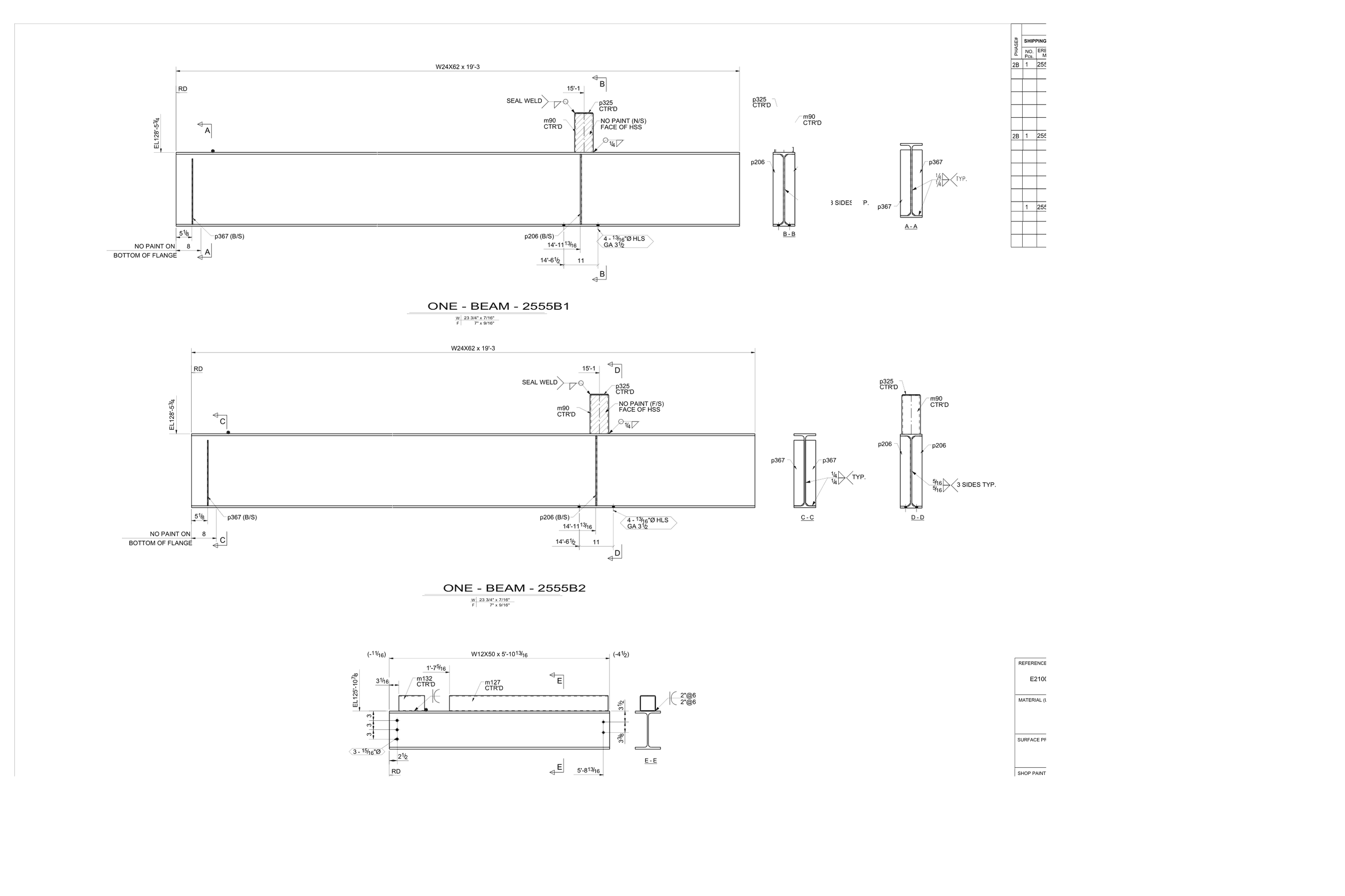
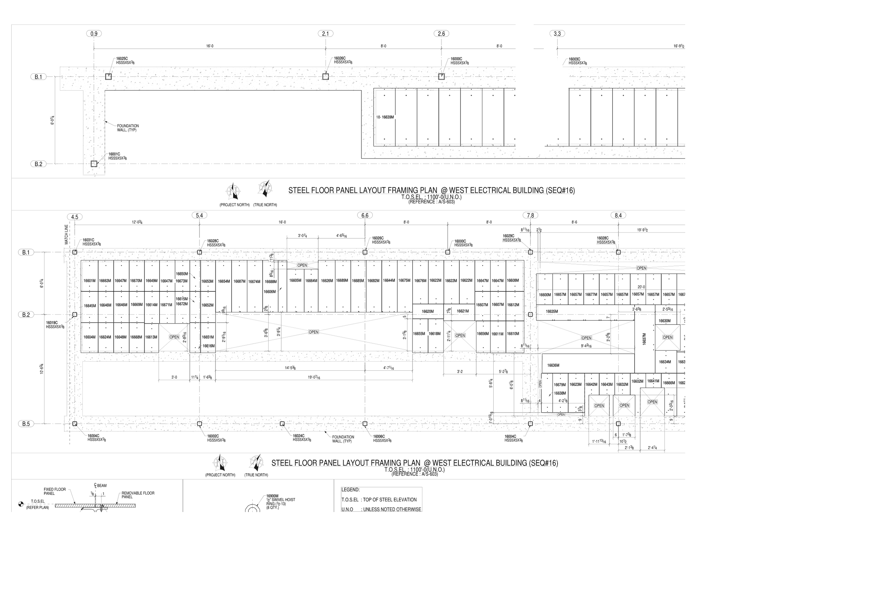
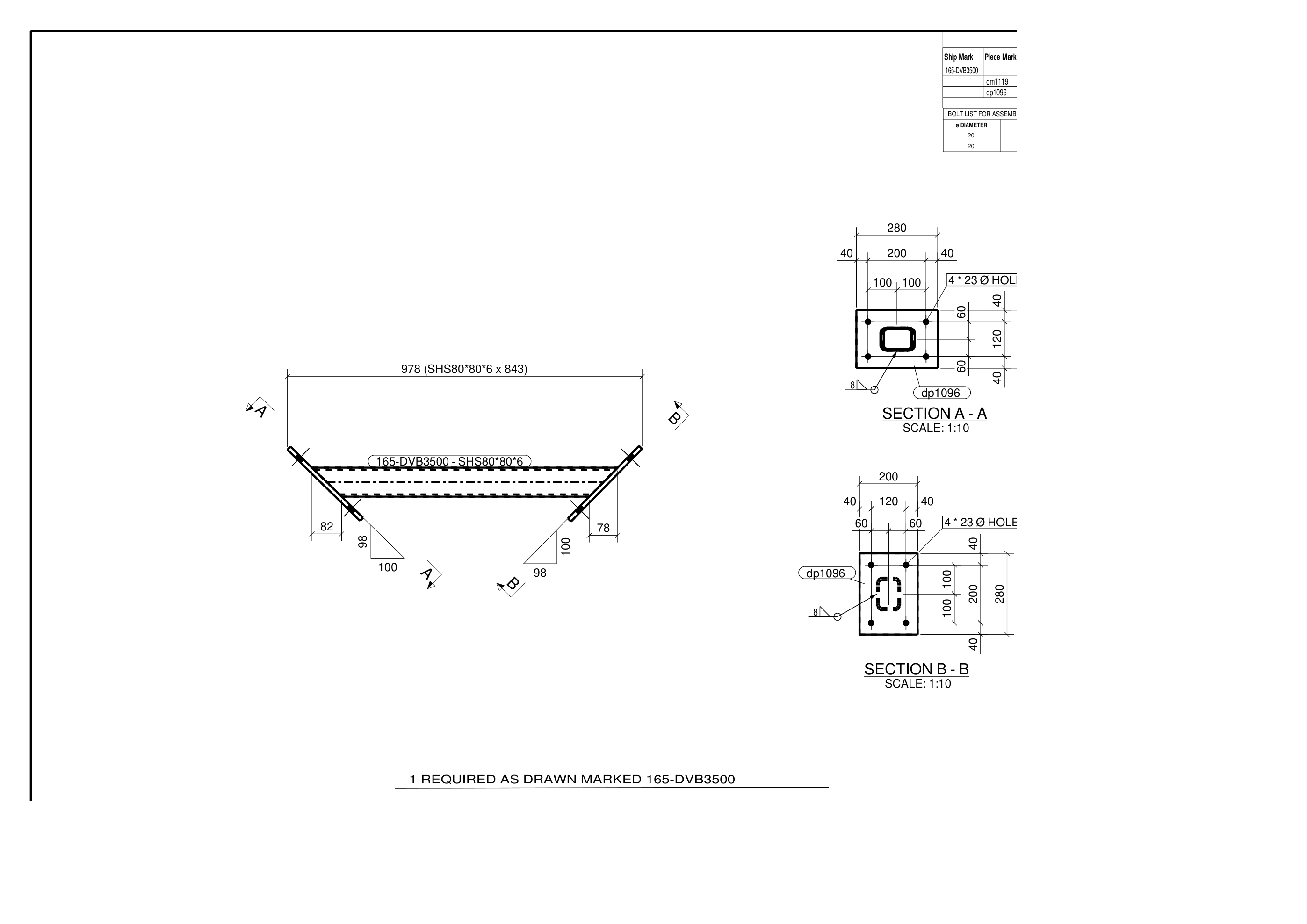
Twelve unrelated sheets: plans, member details, assemblies, splices and cutting profiles. Each one is shown at 1800 px; click any sheet to open it full size (2800 px) in a new tab, which is the resolution at which the dimension strings, bolt lists and weld symbols are legible.
Three formats, three jobs
| PDF — ~2.2M | The issued sheet as it was released, one sheet per file, so a sheet is addressable on its own. |
| DWG — ~139K | The editable source of the sheet. Layers, blocks and text survive, so a sheet can be reopened and interrogated rather than only read. |
| DXF — ~584K | Not sheets at all. One cut outline per file: the closed profile of a single plate or piece in real units, with its holes and copes. This is the format that sits closest to the machine. |
| File class | Distinct files | Volume (GB) |
|---|---|---|
| Vector CAD drawings (PDF) | ~2.2M | ~500 |
| DWG | ~139K | 176.1 |
| DXF piece outlines | ~584K | 69.2 |
| CNC programs (NC1) | ~991K | 1.6 |
The vector CAD row is approximate on both columns, so these rows do not add to the 2D total. NC1 is set apart because it is a program rather than a drawing.
The machine layer: ~991K CNC programs
NC1 / DSTV programs are plain text and machine-readable. A program is not a picture of a part; it is the part as a machine is told to make it. The header names the job, the piece mark, the order number, the steel grade, the quantity, the profile call-out and the overall dimensions; the blocks after it give hole positions and the outer contour as coordinates.
Because the fields are fixed and the file is text, this layer is parseable at scale with no CAD kernel: getting on for a million individually labelled parts with grade, profile, thickness and geometry already separated into fields. That is why it belongs with 2D rather than with the models — it is per-piece fabrication data, the same thing the detail sheet says, in a form a program can read.
Supporting data
18,763 Excel / ABM sheets, 7.9 GB — advance bills of material, shipping and sequence lists: what has to be made, how many, in what grade, for which sequence. Alongside them sit 1,151 BOM join tables, already row-structured.
Where 3D and 2D meet: one plate, three files
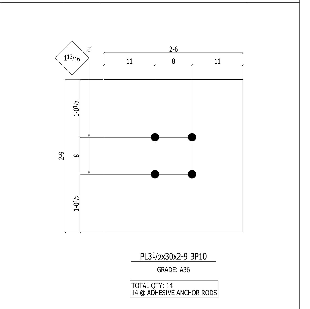
The piece mark is the key. Here is mark BP10 as it appears in the shop drawing, in the cut outline and in the machine program.

ST
  IDI2A_JOB
  BP10_27428
  316
  BP10
  A36
  14
  PL3 1/2X30
  B
  838.20
  762.00
  0.00
  0.00
  88.90
  0.00
  584.879
  0.000
  0.000
  0.000
  0.000
  0.000


BO
  v      317.50u     482.60m    0.00    0.00
  v      317.50u     279.40m    0.00    0.00
  v      520.70u     482.60m    0.00    0.00
  v      520.70u     279.40m    0.00    0.00
AK
  v        0.00u       0.00     0.00
  v      838.20u       0.00     0.00
  v      838.20u     762.00     0.00
  v        0.00u     762.00     0.00
  v        0.00u       0.00     0.00
EN
| Fact | Drawing | DXF | NC1 |
|---|---|---|---|
| Piece mark | BP10 | filename BP10.dxf | BP10 |
| Profile | PL3½x30x2-9 | — | PL3 1/2X30 |
| Grade | A36 | — | A36 |
| Quantity | 14 | — | 14 |
| Plate size | 2-6 × 2-9 | 33.00 × 30.00 in | 838.20 × 762.00 mm |
| Thickness | 3½ in | — | 88.90 mm |
| Hole gauge | 11 + 8 + 11 and 1-0½ + 8 + 1-0½ | — | 279.40 / 482.60 and 317.50 / 520.70 mm |
And at scale
The same key holds well beyond the worked example: more than 386,000 CNC programs are filed beside a DXF cut outline carrying exactly the same piece-mark filename, and more than 430,000 beside a PDF of the same name. Both are floors.